--- The Stude's 2013 Changes Page 22 --- --- Wing &Vertical Stabilizers -- Part IV --- |
One thing that drew a number of comments from people was the helicopter blade that we were going to use for the rear wing. We had looked for a smaller one to no avail and then ....
...the larger one became available so Hooley proceeded to adopt it to the vertical stabilizer frameworks he had built as that was our only option at the time. I became more convinced that we needed to start with something smaller. He was on his way to Utah with the car and I had finished welding up the vertical stabilizers and Bill, Frank and Charlie were applying tons of bondo to them. I awoke about 4 a.m. on Monday, Hooley's second day on the road, and laid in bed and designed a smaller wing in my head that I thought we could build over the next day or so.
Before I go any further let it be made perfectly clear that this wing that follows is purely from my mind and is not based on any know wing shape and I don't lay claim to knowing its characteristics so don't copy it thinking that it is a proven shape other than what it has done for us, which we have no real data on. If you do copy it you are doing so without any recourse to myself or Hooley or any of the crew knowing full well that this wing is purely experimental.
I designed the wing to be as symmetrical as possible under the build conditions. Hopefully it is very neutral until tilted to some angle of attach. The primary consideration besides that was to make it as aero as possible. It has a 1/2 inch half round leading edge. Grows to a little under 7/8 of an inch at its thickest and tapers to the trailing edge at under 7 degrees.
So onto the build...
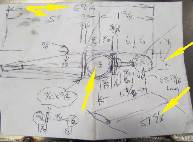
I decided on a solid round 3/4 inch diameter piece of cold rolled steel for the main piece of the wing. I wanted 3/16 X 3/4 strap welded to both sides but had to settle for 1/8 X 3/4 strap instead. The leading edge is 1/2 inch diameter cold rolled steel that we threaded on both ends. The width was 57 - 5/16 inches.
1/8 th inch strap was used for the trailing edge and for the pieces that attach the trailing edge to the center section. The trailing edge was place far enough back to keep the skin angles to it under 7 degrees.
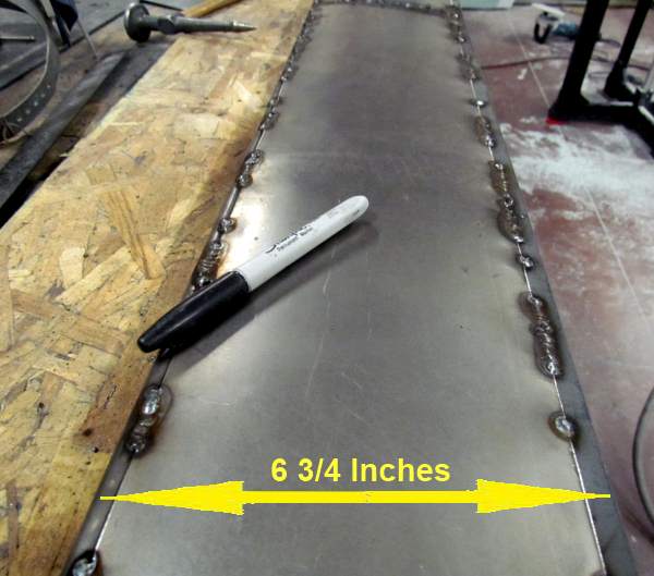
Above the wing's cord (front to back) is shown at 6-9/16 but ended up at 6-3/4 inches.
Ken took the solid 1/2 inch leading edge and put 1/2 inch threads on both ends. The end caps were made to work with the adjustment slots in the vertical stabilizers.
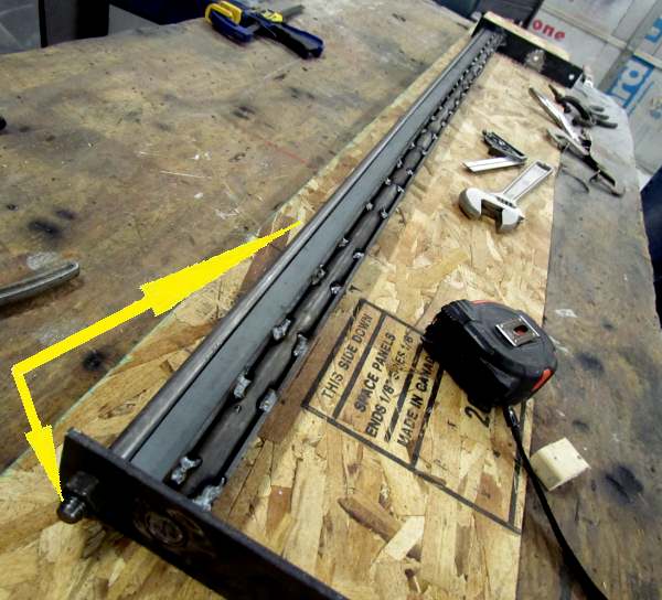
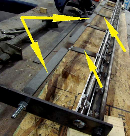
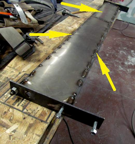
Above the 1/8th X 3/4 pieces of strap have been welded to the sides of the 3/4 inch cold rolled round stock. There is another piece of strap between the leading edge 1/2 inch round stock and the main center section. The plans further up the page imply that the strap is 1/2 inch wide but I don't think that is the case. It looks more like 3/4 or 1 inch. Sorry for the confusion, but this wing was designed and built, other than the bondo, in one day.
As mentioned above the end plates were made to work in the same way that the helicopter blade and its end plates would work.
Next straps were tacked to the main center section and located the trailing edge piece of strap. From the picture above it looks like the strap between the leading edge and the main section is 3/4 inch wide.
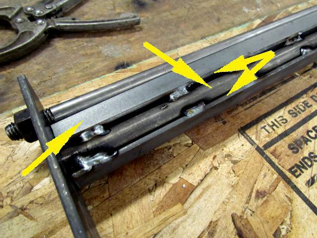
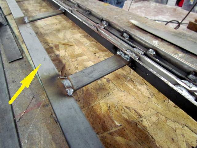
Another view of the trailing edge. Care was taken to make sure the trailing edge was centered behind the main section.
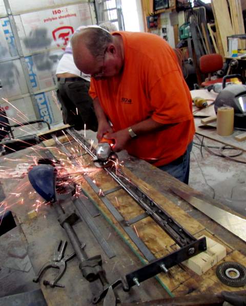
Ken helped me immensely in the build of this wing allowing me to work on some other items. Here he is grinding any welds that were too high, which would interfere with the skin going on.
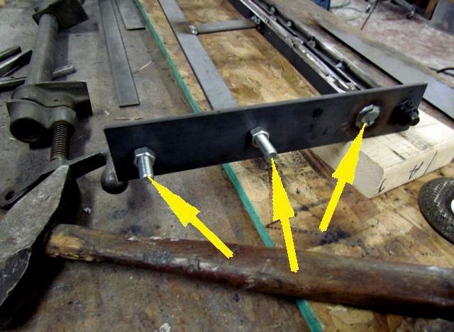
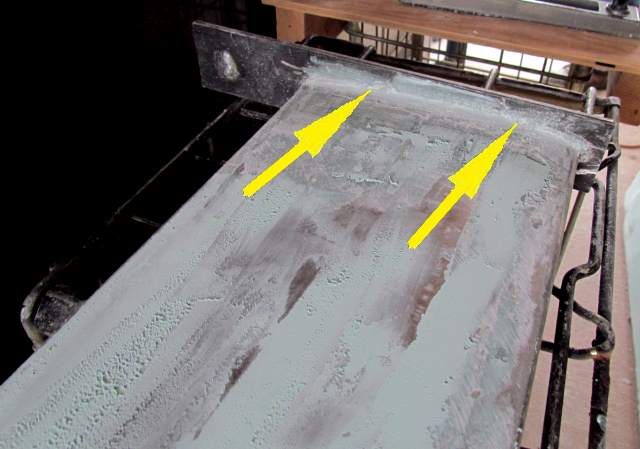
The main section was welded inside and out to the end plates, right arrow. Next two grade 5 bolts were welded to the end plates. The left one pulled out later due to a bad weld on my part :-(. Since it was behind the small wing we just replaced it with a bolt and nut.
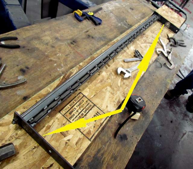
Next came the skin. It was laid on the center section and then rotated down to the leading edge and tacked a number of places there. At this point it was pointed up from the center section towards the trailing edge. It was then bent down to the trailing edge and tack welded there. This produced a nice curved surface from the leading edge to the trailing edge.
To make better use of the material on hand, 20 gauge cold rolled sheet, a separate piece was used to fill in the end of the wing, to arrow, on both sides.
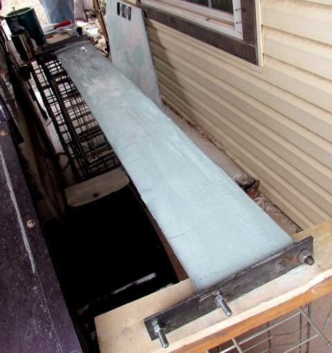
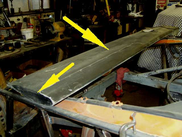
The wing came out quite nice and after this picture was take was weld fully on both sides at the leading and trailing edges. Notice the width.
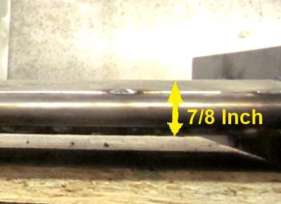
This is a frontal view and shows the less than 7/8 th total thickness at the thickest part of the wing. Not much frontal area. Less than .35 square feet for the wing alone [(57 inches wide X .875 inches high)/ 144 sq. inches].
I'm hoping that the Cd is .1 or less so the CdA would then be less than .035 [(57 inches wide X .875 inches high)/144 sq. in. X .1 Cd]. I'm hoping that the CdA of each vertical stabilizers is also around .035 [(33 X .75)/144 X .2], but this is just a guess as well as the figure for the wing. I believe the wing is considerably more aero than the vertical stabilizers.
If the above guesses are close then the total drag for the verticals and the wing would be around .1 (CdA). Not bad for the benefits. Now once the wing is tilted for downforce this number should go up slightly.
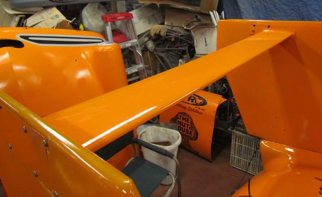
Above is a picture of the other wing, the helicopter blade that is also symmetrical in shape which should result in no lift or downforce when parallel with the ground. It is 12 1/2 inches front to back and 2 inches thick so possible over twice the drag of the smaller wing.
After Ken and I knocked the wing out in one day Charlie took over and applied bondo to it.
It didn't require near the work that the stabilizers did to get straight.
Before Charlie got the wing I had also welded the wings perimeter where it meet the end plates and ground the welds down.
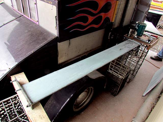
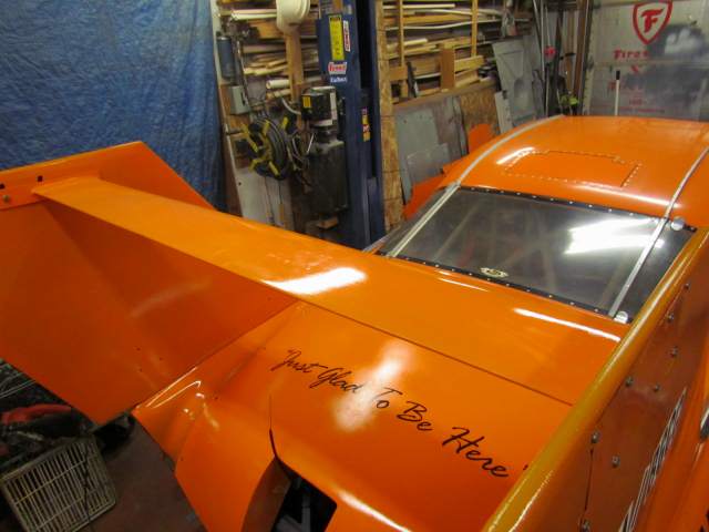
The wing on the car prior to final painting.
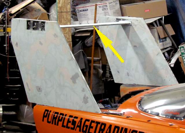
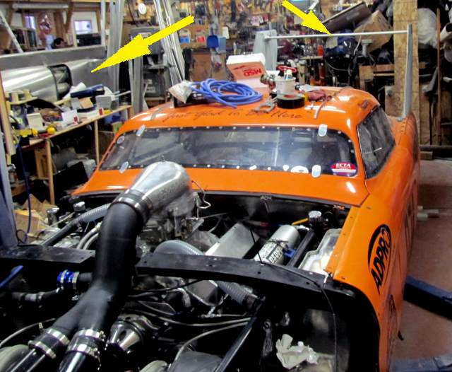
A frontal shot with the large arrow pointing at my attempt at building a lakester that has now been on hold for some time.
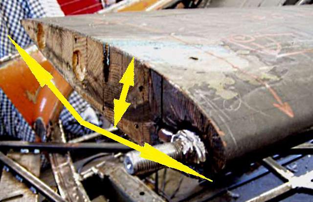
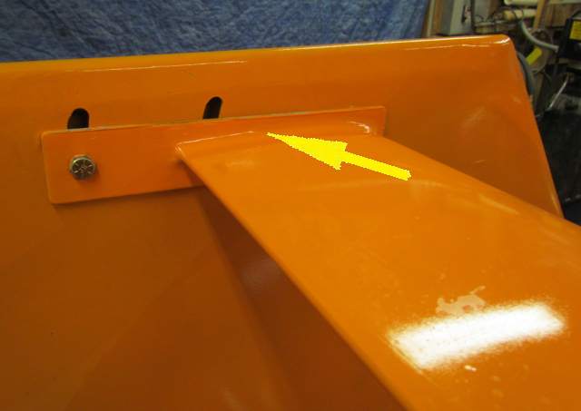
The arrow points to where the wing is welded around its perimeter to the mounting plate. To the left is the bolt that replaced the failed stud. The other side was also replace with a bolt.
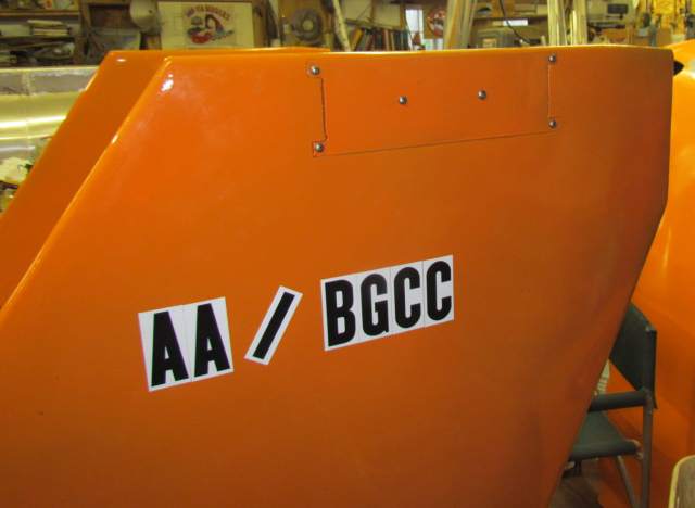
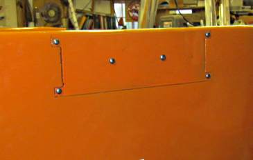
A view of the plate that....
.... is held on with some stainless steel screws and is removed to adjust the wing. We ended up with the wing set to 2 degrees on our final runs at SpeedWeek 2013.
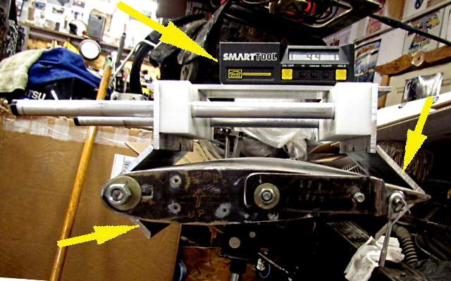
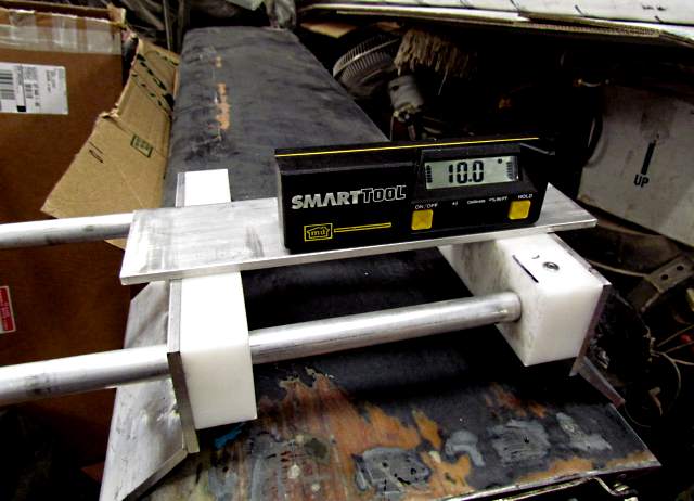
Mark Maupin, the crew chief, made this handy inclinometer to set the wing angle.
It will work on either the large wing (shown above in the shop off the car) or on the smaller wing shown below.
The wing is very strong and I feel that it won't fail with any downforce it is capable of creating.
When/if you read the story of this year's runs you will see that the wing and verticals saved the car from a total spin when the throttle stuck wide open. They were subjected to the car being at least 60 degrees or more out of shape before they caught the car and sent it back the other way. On the second swing I got the chute out and the car settled down and went straight and was driven to the return road with no damage.
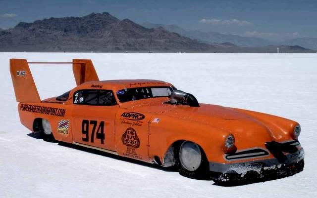
A picture of the car on the salt taken by Tom. At this point we are very happy with the wing and vertical stabilizers and their performance. There will be more updates after the car runs faster than the 217+ that it ran on a license run at SpeedWeek 2013.